| 1. Select the Container |
Common large-container option |
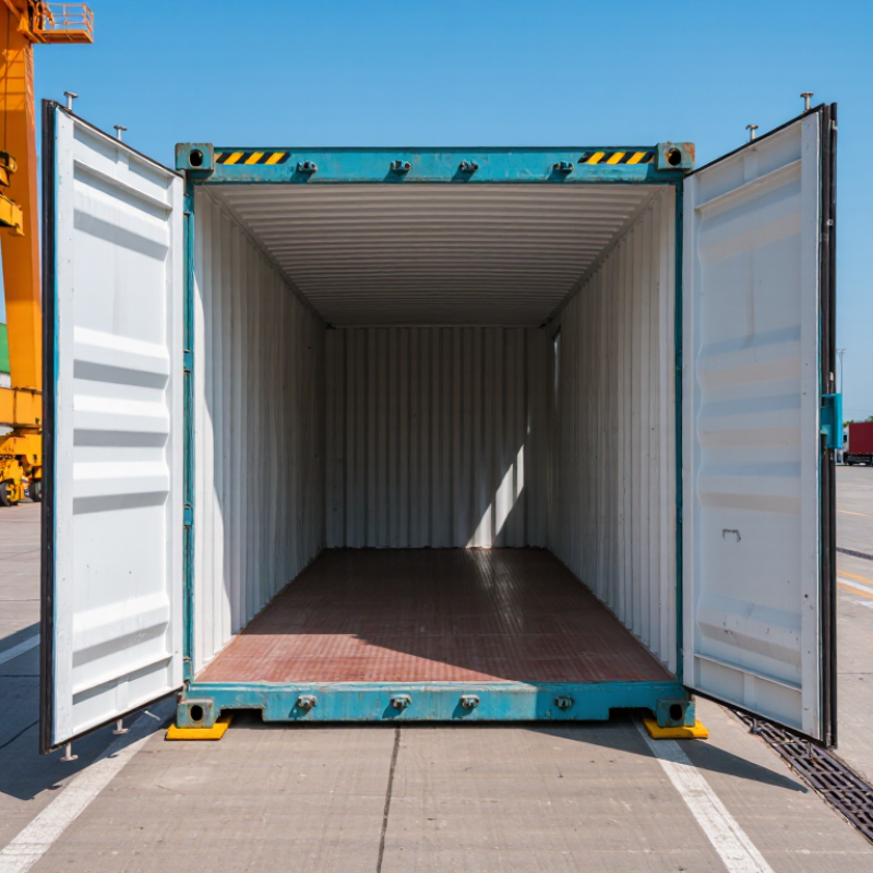
40-foot High Cube; external size is approximately 12.192 m L × 2.438 m W × 2.896 m H. |
Confirm that the extra internal height is needed for equipment, shelving, insulation, or overhead clearance. |
Purchase documents match the selected length, width, height, door configuration, and condition grade. |
| 1. Select the Container |
Internal usable space |
A typical 40-foot High Cube has approximately 12.032 m internal length × 2.350 m internal width × 2.690 m internal height. Actual dimensions vary by construction. |
Measure the largest item, including packaging, and allow clearance for loading, ventilation, and door operation. |
Largest cargo passes through the door opening without removing structural components. |
| 1. Select the Container |
Door opening |
A typical 40-foot High Cube door opening is approximately 2.340 m wide × 2.585 m high. |
Check the height and width of all cargo, handling equipment, and access routes before ordering. |
Door seals, locking bars, hinges, and locking rods operate smoothly. |
| 1. Select the Container |
Weight planning |
Typical tare weight is about 3,800–4,200 kg; maximum gross mass is commonly up to 30,480 kg. Payload depends on the individual container plate and local transport limits. |
Use the container data plate and shipping documents rather than relying only on standard specifications. |
Tare weight, maximum gross mass, and intended cargo weight are recorded in the purchase file. |
| 2. Verify the Site |
Access width and height |
Provide a route wider than the container trailer and allow overhead clearance above the container, trailer, trees, cables, signs, and structures. |
Conduct a route survey from the delivery road to the final position. Record narrow turns, slopes, bridges, gates, and overhead obstructions. |
Transport equipment can enter, turn, stop, and leave without striking property or utilities. |
| 2. Verify the Site |
Ground condition |
The placement area should be firm, stable, well-drained, and capable of supporting the concentrated loads at the container corner points. |
Remove organic soil, standing water, loose fill, and debris. Obtain local engineering advice for soft, sloping, or expansive ground. |
No visible rutting, rocking, settlement, or standing water occurs during placement and inspection. |
| 2. Prepare the Foundation |
Support arrangement |
Use four durable support points aligned with the container corner castings. Concrete pads, reinforced foundations, or engineered alternatives may be used. |
Keep the container supported at its structural corners and maintain drainage beneath the floor. |
All four corner points are fully supported, aligned, and free from unstable gaps. |
| 2. Prepare the Foundation |
Foundation footprint |
For a 40-foot container, the support layout follows the container length of approximately 12.192 m and width of approximately 2.438 m. |
Set out the foundation using the actual container dimensions and corner-casting locations supplied with the unit. |
Support points do not obstruct doors, drainage, twist-lock fittings, or underfloor inspection areas. |
| 3. Arrange Transport |
Trailer and legal dimensions |
A loaded road combination may exceed ordinary vehicle dimensions and weight limits. Requirements vary by jurisdiction, route, and container weight. |
Give the carrier the container length, height, tare weight, cargo weight, delivery address, and site restrictions. |
Carrier confirms the suitable trailer, route, permits, escort requirements, and delivery appointment. |
| 3. Arrange Transport |
Delivery access |
Delivery may require a chassis, tilt-bed trailer, side-loader, or crane-assisted vehicle depending on the final placement distance and site conditions. |
Choose equipment based on whether the container can be placed directly beside the trailer or must be lifted over an obstruction. |
Delivery method is confirmed in writing, including maximum reach, placement direction, and unloading sequence. |
| 3. Arrange Transport |
Weather and scheduling |
Strong wind, heavy rain, snow, flooding, or poor ground conditions can make lifting and positioning unsafe. |
Schedule delivery during suitable daylight and weather conditions, with a backup date available. |
Site supervisor and carrier agree that the ground and weather are safe before unloading begins. |
| 4. Prepare for Delivery |
Clearance zone |
Keep the placement area and equipment path clear of people, vehicles, materials, branches, cables, and temporary structures. |
Mark the container footprint and establish an exclusion zone for unloading and lifting operations. |
No unauthorized person enters the lifting or unloading zone. |
| 4. Prepare for Delivery |
Lifting points |
Container lifting should use the approved corner castings and compatible lifting equipment. A spreader arrangement helps maintain appropriate lifting geometry. |
Use a qualified lifting contractor and follow the container manufacturer's lifting instructions and the lifting equipment's rated capacity. |
Slings, shackles, spreader equipment, crane capacity, and lift plan are inspected before work starts. |
| 5. Final Installation |
Position and orientation |
Door orientation should support safe access, drainage, ventilation, and future maintenance. Avoid directing doors toward flood-prone or obstructed areas. |
Confirm the final orientation before the container leaves the trailer or crane hook. |
Doors open fully, delivery access remains usable, and rainwater drains away from the container. |
| 5. Final Installation |
Level and alignment |
The container should sit level enough for reliable door operation and even load transfer. Exact tolerances depend on the foundation design and intended use. |
Check the floor, corner castings, doors, and frame after placement. Use engineered shims only where appropriate. |
Doors open and close without binding, the frame is not visibly twisted, and all supports remain stable. |
| 5. Final Installation |
Anchoring and security |
Anchoring may be required for wind, seismic activity, theft prevention, public access, or local building rules. |
Use an engineer-approved anchoring method appropriate for the foundation and local hazards. |
Anchors, locks, and any anti-tamper devices are installed and documented. |
| 6. Final Inspection |
Structural condition |
Inspect corner posts, top and bottom rails, side panels, roof, floor, doors, seals, and welds for damage, deformation, corrosion, or leaks. |
Photograph all sides and record defects before accepting delivery. |
Any damage is listed on the delivery document and assigned for repair or compensation. |
| 6. Final Inspection |
Ventilation and moisture control |
Closed steel containers can experience condensation from temperature changes, especially when cargo is wet or airflow is limited. |
Use dry cargo, maintain ventilation where appropriate, and add insulation or vapor control only after assessing the intended use. |
Interior is dry, odor-free, free of active leaks, and suitable for the planned cargo or conversion. |
| 7. Documentation |
Required records |
Maintain the purchase invoice, container identification, data plate details, delivery record, inspection photos, foundation information, and permits where applicable. |
Keep the documents with the site and asset records for future relocation, resale, insurance, or maintenance. |
All specifications, approvals, inspection results, and delivery conditions are stored together. |
| Planning note: Dimensions, weights, permits, road restrictions, foundation requirements, lifting methods, and installation rules vary by container construction, location, cargo, soil, weather, and local regulations. Confirm final values with the container data plate, a qualified carrier, and local construction or lifting professionals before purchase and delivery. |