
Why Grounding Transformer Matters for Global Buyers?
For global buyers, a Grounding Transformer is more than another component inside a substation. It can create a neutral point for systems that lack one, especially delta-connected networks. This arrangement gives fault protection equipment a clearer path during earth faults. It may also help stabilize system voltage under abnormal conditions. However, the correct design depends on voltage level, fault-current limits, insulation coordination, and local grid requirements.
A practical purchasing decision should begin with the operating environment. Consider a dusty factory, a coastal wind farm, or a compact urban substation. Each location creates different thermal, mechanical, and maintenance demands. Buyers should review the transformer’s rated power, grounding method, impedance, cooling system, enclosure, and expected service life. Test reports, routine inspection records, and factory acceptance procedures provide stronger evidence than attractive catalog claims. IEC or IEEE references can support evaluation, but local utility rules still control final acceptance.
Small details matter.
For example, protection relays must match the grounding design and resistor settings. Incorrect coordination can cause delayed fault clearing or unnecessary shutdowns. Experienced suppliers should explain these risks with drawings, calculation sheets, and field references. Yet no specification is perfect. Actual site conditions may differ from the original assumptions. That possibility deserves honest discussion before purchase. A reliable global buyer therefore compares engineering support, documentation quality, logistics, warranty terms, and after-sales response together. The cheapest Grounding Transformer may not deliver the lowest lifetime cost. Careful verification protects both equipment and people.
What Is a Grounding Transformer and How Does It Work?
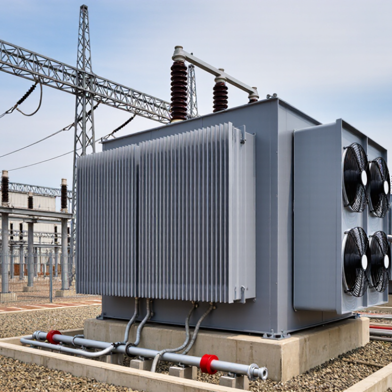
A grounding transformer creates a neutral point on a system without a grounded neutral. It connects to the three-phase network and provides a controlled path for zero-sequence fault current. Common designs include zigzag and wye-delta transformers. The choice depends on voltage, fault-current limits, relay settings, and operating conditions.
Its main job is protection, not ordinary load supply. During a single-line-to-ground fault, it helps stabilize phase-to-ground voltage and gives protection equipment a measurable current path. A neutral grounding resistor may limit that current and reduce equipment damage. This matters as grids become more complex. The International Energy Agency reported 473 GW of renewable capacity additions in 2023. Its 2023 grid report also estimated that 80 million kilometres of grids must be added or refurbished by 2040. More distributed generation means more grounding questions.
A grounding transformer is not automatically the safest choice. Poor coordination can cause nuisance trips or dangerous touch voltages. I have seen specifications focus on rated voltage while overlooking temporary overvoltage and thermal duty. That assumption is risky. Buyers should verify fault-current duration, insulation level, neutral grounding method, zero-sequence impedance, and maintenance access. IEC 60076 guidance and local grid codes should support the technical review.
Tips: Request a short-circuit study before ordering. Confirm whether the transformer must carry continuous unbalance current. Ask for factory test records, protection coordination data, and installation references from similar network conditions. Small details matter.
| Category | Engineering Dimension | Fact-Based Technical Information | Why It Matters to Global Buyers |
|---|---|---|---|
| Definition | Primary function | A grounding transformer creates an artificial neutral point on a three-phase system that does not have a directly accessible neutral. | It enables controlled connection of the system to earth and provides a defined path for zero-sequence current during an earth fault. |
| Operating Principle | Fault-current path | During a single-line-to-ground fault, current flows through the phase conductor, the fault point, the grounding connection, and the transformer neutral path. | A predictable fault path allows protection systems to detect and clear faults more reliably. |
| Common Design | Zig-zag configuration | A zig-zag grounding transformer provides a neutral point and offers a low-impedance path to zero-sequence current while generally presenting higher impedance to balanced three-phase current. | It is often selected when a compact grounding solution is required without a conventional secondary load winding. |
| Common Design | Wye-delta configuration | The grounded wye side provides the neutral connection, while the delta side can circulate triplen-frequency components and may supply auxiliary power when specifically designed for that purpose. | This arrangement can combine system grounding with a usable low-voltage auxiliary supply. |
| Neutral Grounding | Neutral grounding resistor | A resistor connected between the transformer neutral and earth limits ground-fault current to a selected value. | Limiting current reduces thermal and mechanical damage while maintaining enough current for protective relays to identify the fault. |
| Example Calculation | Ground-fault current | For an 11 kV line-to-line system with a 20 Ω neutral grounding resistor: I ≈ 11,000 ÷ (√3 × 20) = 317.5 A, excluding system and transformer impedance. | The calculation helps buyers compare resistor ratings, relay settings, earthing conductors, and short-time thermal withstand requirements. |
| Grounding Method | Solid grounding | The neutral is connected to earth with negligible intentional impedance, allowing relatively high earth-fault current. | It supports fast fault clearing but may increase equipment stress and requires suitable interrupting and grounding capacity. |
| Grounding Method | Low-resistance grounding | The neutral resistor is selected to permit a comparatively high but controlled fault current, commonly in the hundreds of amperes for medium-voltage industrial systems. | It provides strong relay sensitivity while limiting damage compared with solid grounding. |
| Grounding Method | High-resistance grounding | The neutral resistor limits the fault current to a low value, often near or below the system’s charging-current level, subject to the network design. | It can reduce arc-flash energy and allow continued operation for a limited period, but requires sensitive ground-fault monitoring. |
| Protection | Zero-sequence protection | Grounding transformers support measurement of zero-sequence voltage or current, which is used by earth-fault relays and ground-fault protection systems. | Protection settings can be coordinated with the selected transformer impedance and neutral grounding resistor. |
| System Compatibility | Typical applications | Common applications include medium-voltage distribution networks, industrial plants, renewable-energy collector systems, mining facilities, and isolated three-phase networks. | Application type determines the required voltage rating, fault-current duration, insulation level, enclosure, cooling, and protection scheme. |
| Rating | Continuous and short-time duty | A grounding transformer is normally sized for the required ground-fault current and its duration, rather than for the full continuous load of the connected power system. | Buyers should specify continuous duty, short-time current, duration, temperature rise, and permissible neutral displacement separately. |
| Technical Standards | Specification framework | Relevant project requirements may reference IEC 60076-6 for reactors, IEC 61936-1 for power installations above 1 kV AC, IEEE 32 for neutral grounding devices, and applicable local grid codes. | Using the correct regional standards improves tender comparability, inspection planning, certification, and project approval. |
| Buyer Checklist | Key parameters to request | System voltage, frequency, grounding method, neutral current, fault duration, transformer connection, impedance, insulation level, enclosure rating, cooling method, environmental conditions, and applicable standard. | A complete specification reduces redesign risk, prevents mismatched protection settings, and supports reliable operation across different grid conditions. |