
Why Choose CNC Milling for Precision Manufacturing?
Why Choose CNC Milling for Precision Manufacturing?
CNC Milling has become a practical choice for manufacturers that need accurate, repeatable, and complex parts. A computer-controlled cutter can shape aluminum, steel, plastics, and engineered materials with controlled movements across multiple axes. It can produce pockets, slots, contours, and drilled features from one digital model. That reduces manual handling and limits alignment errors.
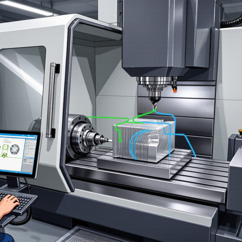
The difference appears on the shop floor. A stable fixture holds a metal block, while the spindle removes thin layers with measured consistency. Tool paths can be adjusted before cutting begins. This helps engineers identify collisions, excess material, and inefficient movements earlier. It also supports repeat production, where the tenth component should closely match the first.
Yet CNC Milling is not magic. Poor fixturing still causes vibration. Worn tools still damage surfaces. An inaccurate drawing can produce a perfectly machined wrong part. These limitations deserve attention, especially when tolerances become extremely tight. Skilled machinists, inspection equipment, and disciplined process control remain essential.
Gene Haas, founder of Haas Automation, expresses this practical responsibility clearly: “We’re not in the machine tool business; we’re in the business of making our customers successful.” His statement reflects an important manufacturing truth. The machine is only one part of the result. Material selection, programming, cutting parameters, inspection, and operator experience all influence final quality.
This article examines why CNC Milling remains valuable for precision manufacturing. It considers accuracy, repeatability, flexibility, production efficiency, surface quality, and cost control. It also questions when CNC Milling may not be the best option. That balance matters. Precision is not achieved by equipment alone. It is built through careful decisions, measurable processes, and continuous review.
What Is CNC Milling in Precision Manufacturing?
CNC milling is a subtractive process that shapes metal or plastic with rotating cutting tools. A computer numerical control system guides each movement from a digital design. The machine removes material layer by layer, creating slots, holes, pockets, and contoured surfaces.
Small detail matters.
In precision manufacturing, CNC milling connects design intent with repeatable physical results. Operators select cutting speed, feed rate, tool geometry, and workholding methods. These choices influence surface finish and dimensional accuracy. ISO 230-2 provides methods for testing machine-tool positioning accuracy and repeatability. It does not eliminate process variation. Heat, vibration, and tool wear still require attention.
Market data reflects this growing role. Grand View Research estimated the global CNC machine market at about 83 billion U.S. dollars in 2023, with continued growth expected through 2030. Deloitte’s 2024 Smart Manufacturing and Operations Survey reported that 86% of manufacturing leaders viewed smart manufacturing as a major competitiveness driver. CNC milling supports that shift through digital programs, measurable offsets, and production records.
On a shop floor, a well-prepared setup can hold tight tolerances across repeated parts. A machinist may inspect the first component, adjust tool compensation, and check the final edge under magnification. Still, CNC milling is not automatically precise. Poor clamping or thermal drift can ruin an otherwise accurate program. A cautious engineer should verify the process, not simply trust the machine.
| Data Dimension | CNC Milling Information | Relevance to Precision Manufacturing |
|---|---|---|
| Process Definition | CNC milling is a subtractive manufacturing process in which a computer-controlled rotary cutting tool removes material from a stationary or secured workpiece. | The programmed tool paths provide repeatable control over dimensions, profiles, holes, pockets, slots, and complex three-dimensional surfaces. |
| Machine Axes | Common configurations include 3-axis milling, while 4-axis and 5-axis machines add rotary movement for better access to angled or complex features. | Additional axes can reduce repositioning, improve feature alignment, and help produce complex parts in fewer setups. |
| Typical Dimensional Tolerance | Approximately ±0.025 mm to ±0.125 mm is common for many CNC-milled features, depending on material, machine condition, tool selection, geometry, and inspection method. | CNC milling is suitable for components that require controlled fits, consistent hole locations, and repeatable dimensional performance. |
| Surface Finish | Machined surface roughness commonly ranges from about Ra 0.8 to 6.3 µm, although tooling, cutting parameters, material, and finishing passes can produce different results. | Finishing passes and optimized cutting conditions can improve appearance, sliding performance, sealing surfaces, and dimensional consistency. |
| Compatible Materials | Frequently machined materials include aluminum alloys, steels, stainless steels, brass, copper, titanium, engineering plastics, and selected composite materials. | Material flexibility supports prototypes, tooling, machine components, enclosures, brackets, fixtures, and production parts across many industries. |
| Geometric Capability | CNC milling can produce flat surfaces, steps, contours, pockets, keyways, threads, drilled features, chamfers, and three-dimensional sculpted surfaces. | A single process can combine multiple feature types, reducing the need for separate operations and helping maintain feature-to-feature accuracy. |
| Repeatability | Once the program, workholding, tools, and inspection controls are validated, the same machining sequence can be repeated for multiple parts. | Repeatable production helps maintain consistent dimensions and reduces variation between batches compared with manually controlled machining. |
| Production Volume | CNC milling is practical for one-off prototypes, low-volume custom parts, pilot batches, and medium-volume production. | The same digital design data can be used for development and production, reducing the transition time between prototype and manufactured part. |
| Design Flexibility | Tool paths can be generated from CAD models and adjusted for changes in dimensions, materials, tolerances, or feature locations. | Design revisions can usually be implemented through digital program updates without creating dedicated hard tooling for every change. |
| Setup Requirements | Production requires workholding, tool selection, cutting parameters, coordinate setting, program verification, and appropriate inspection. | Careful setup planning is essential because workpiece alignment, tool wear, thermal effects, and fixturing directly influence final accuracy. |
| Material Utilization | CNC milling removes material from a larger blank, so chips and offcuts are generated during machining. | It can be less material-efficient than near-net-shape processes for heavily sculpted parts, but many metal chips can be collected and recycled. |
| Quality Control | Inspection may include calipers, micrometers, height gauges, gauges, coordinate measuring machines, and surface-finish instruments. | Measurement results can verify critical dimensions, geometric relationships, hole positions, and surface requirements before shipment. |
| Common Applications | Typical applications include precision brackets, housings, fixtures, molds, machine components, prototypes, medical-device parts, and aerospace structures. | The process is valuable where accuracy, repeatability, complex geometry, and traceable digital production data are important. |
| Main Advantages | High repeatability, broad material compatibility, efficient digital control, flexible part geometry, and the ability to produce accurate features in relatively small quantities. | These characteristics make CNC milling a strong choice when product quality and design adaptability are more important than achieving the lowest cost at extremely high volumes. |
| Technical note: Values shown are typical industry ranges and general process characteristics. Actual results depend on machine capability, material condition, part geometry, tooling, workholding, programming, environmental control, and inspection practice. | ||