
en es

How to Use a Digital Crimper for Precise Connections?

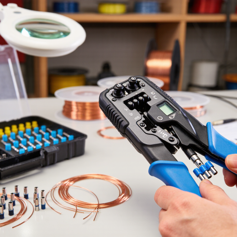
Making precise electrical connections requires more than squeezing a handle and hoping for a clean result. A Digital Crimper combines controlled pressure with electronic feedback, helping technicians create consistent terminals across repeated jobs. Its display may show force, cycle data, or setting information, depending on the model. These details can reduce guesswork when working with copper wire, insulated terminals, and carefully specified connector systems.

Accuracy begins before the crimping cycle. Select the correct die for the terminal and wire size. Check the conductor for damaged strands, oxidation, or uneven stripping. Place the terminal squarely, then insert the wire until the conductor reaches the required stop. Small errors matter. After crimping, inspect the barrel for distortion, loose strands, or incomplete compression. A gentle pull test can reveal weakness that looks invisible at first glance. For critical work, follow the connector manufacturer’s specifications and record tool settings for repeatability.

A Digital Crimper is helpful, but it is not foolproof. Displays can be misunderstood, batteries can weaken, and tools can lose calibration through heavy use. I have found that a quick visual check often catches problems before testing does. That habit may seem slow. It protects reliability. This guide explains practical setup, operating technique, inspection steps, and maintenance practices for achieving dependable connections without relying on pressure alone.
How to Use a Digital Crimper for Precise Connections?

Understanding Digital Crimper Components and Connection Requirements

A digital crimper creates repeatable electrical and mechanical connections when its components match the terminal system. The die set shapes the terminal. The locator holds it in position. A force sensor detects incomplete compression, while the display records pressure, cycle count, and error codes. Some models also store calibration histories. That record matters during audits.

Connection requirements must be checked before the cable enters the tool. Confirm the conductor size, terminal material, insulation diameter, and approved crimp profile. The wire should reach the correct stop without excessive stripping. Copper strands must remain aligned. A loose strand can weaken the joint.

IPC/WHMA-A-620E provides workmanship criteria for cable and wire-harness assemblies, including crimp appearance and inspection points. IEC 60352-2 also defines requirements for solderless crimped connections and mechanical performance.

Demand for reliable harness work is rising. The International Energy Agency reported over 14 million electric cars sold worldwide in 2023. More vehicles mean more compact, vibration-sensitive connections. A digital tool helps control variation, but it cannot correct the wrong die. It cannot repair damaged strands. It also cannot replace pull testing. The U.S. Federal Aviation Administration emphasizes documented inspection and tool control in aircraft wiring guidance, showing why traceability remains practical, not decorative. In daily work, I still find one weak habit: operators trust the screen too quickly. Check the crimp height. Inspect the bellmouth. Perform a sample pull test. Mistakes become visible there.

Selecting the Correct Terminal, Wire, and Crimping Die

A digital crimper produces reliable connections only when the terminal, wire, and die match. Start by checking the wire gauge and conductor material. A copper terminal may not suit every conductor. Confirm the terminal’s approved wire range before cutting insulation.

Strip the wire carefully, leaving clean strands without nicking them. Insert the conductor until it reaches the terminal’s inspection window. The insulation should enter the support area, but it must not sit inside the conductor barrel. Select a crimping die designed for the terminal shape and wire size. Digital settings can improve repeatability, but they cannot correct a mismatched die. Watch the screen for pressure, cycle completion, and error signals.

After crimping, inspect the barrel for even compression and visible strand placement. Perform a gentle pull test, then compare the result with the specified requirement. I once focused too much on pressure readings and missed a slightly exposed conductor. That mistake reminded me to inspect the connection physically. A clean crimp has firm support, no cracked insulation, and no loose strands. Keep a record of wire size, terminal type, die position, and test results. Small details matter. Recheck questionable connections.

Preparing the Wire and Positioning the Terminal

Preparing the wire correctly determines whether a digital crimper can make a reliable connection. Industry guidance in IPC/WHMA-A-620 stresses controlled stripping, clean conductors, and correct terminal placement. Cut the wire squarely, then strip only the specified length. Excess insulation removal can expose live strands. Too little removal can prevent the conductor from reaching the terminal barrel.

A 2024 wiring-harness market analysis by Grand View Research estimates the sector will grow at about 6.6% annually through 2030. That growth increases pressure for repeatable assembly, not faster guessing. Before crimping, match the wire gauge with the terminal range shown in the approved work instruction. Inspect the strands under bright light. They should remain straight, uncut, and free from oil. Twist only if the procedure allows it.

Position the terminal centrally in the digital crimper’s locator. The conductor barrel should face the correct die cavity, while the insulation support rests behind it. Insert the stripped wire until the conductor reaches the barrel stop. Do not force it. A small misalignment can create uneven compression, even when the screen shows a complete cycle. I sometimes recheck the terminal after a good-looking crimp; appearance is not proof. A pull test, height measurement, or cross-section check may reveal hidden weakness. Record the result when process control matters. Calibration records and operator training support the traceability expected in professional harness production.

How to Use a Digital Crimper for Precise Connections? - Preparing the Wire and Positioning the Terminal
Step Wire Size Approximate Conductor Area Typical Insulation Strip Length Terminal Preparation Positioning and Inspection Criteria Digital Crimper Check
1 22 AWG 0.326 mm² 6–7 mm Select a terminal barrel designed for 22 AWG stranded wire. Insert the conductor until the strands reach the end of the wire barrel without extending beyond it. Use the die cavity marked for 22 AWG or the equivalent conductor range.
2 20 AWG 0.518 mm² 6–8 mm Keep the insulation outside the conductor-crimp section. The conductor should be visible through any inspection window, while insulation remains supported by the insulation-grip section. Confirm that the tool recognizes the selected wire range before starting the cycle.
3 18 AWG 0.823 mm² 7–8 mm Use a clean, undamaged terminal with a barrel length suitable for the stripped section. Center the terminal barrel in the die; do not place the seam directly on the highest compression point unless the terminal instructions allow it. Check that the terminal is held squarely and that the crimp cycle completes without an overload warning.
4 16 AWG 1.31 mm² 8–9 mm Match the terminal's conductor range to 16 AWG stranded wire. Verify that no loose strands are outside the barrel and that the insulation is not trapped in the conductor-crimp area. Select the correct die profile; a larger cavity can produce an under-crimp, while a smaller cavity can damage the conductor.
5 14 AWG 2.08 mm² 9–10 mm Twist the strands lightly only if needed to prevent spreading; do not tin the strands before crimping. Push the wire fully home, then position the terminal so the conductor barrel is centered between the die faces. Review the recorded crimp-force or completion result and compare it with the approved process limits.
6 12 AWG 3.31 mm² 10–11 mm Use a terminal and die specifically rated for 12 AWG conductors. Ensure the insulation support grips the jacket without cutting through it; the conductor must remain fully inside the conductor barrel. Allow the tool to complete its full cycle, then inspect the crimp for symmetry, cracks, deformation, or exposed strands.
7 Any listed wire size Verify against the terminal specification Use the terminal manufacturer's specified strip length when available Keep the terminal clean, dry, and free from burrs or distorted metal. After crimping, the wire should not rotate freely in the terminal, and the terminal should not be visibly cracked or crushed. Record the wire size, terminal type, die setting, crimp result, and inspection status for traceability.
Reference note: AWG-to-area values are standard nominal conversions, while strip lengths are typical working values for many insulated terminals. Always prioritize the terminal and digital crimper manufacturer's approved wire range, strip length, die cavity, and crimp-quality requirements.

Setting Crimp Pressure and Making the Connection

A digital crimper makes pressure easier to control, but accurate connections still require preparation. Match the terminal to the wire size before placing either part into the tool. Check the recommended pressure range in the tool manual or terminal specifications. Never guess from feel alone. The display should show a stable reading before the crimp begins. Clean the dies and remove loose insulation fragments. Small errors matter.

Place the terminal squarely in the correct die. Insert the stripped wire until its conductor reaches the terminal’s metal barrel. The insulation should stop just outside the barrel, not inside it. Set the pressure slightly within the approved range, then lock the setting. Too little pressure can leave gaps and movement. Excessive pressure may cut strands or deform the terminal. Make one smooth crimp. Do not twist the tool during compression.

Inspect the finished connection under bright light. The barrel should grip evenly, with no cracks or exposed damaged strands. A gentle pull test can reveal a weak hold, but it should not replace proper measurement. For critical work, compare the crimp height with the specified value and record the result. I once trusted a clean appearance and missed a loose conductor. That mistake changed my routine. Now I test samples before completing a batch. Digital readings help, yet calibration and operator judgment still decide the connection’s reliability.

How to Use a Digital Crimper for Precise Connections

Setting Crimp Pressure and Making the Connection

Use the digital crimper’s pressure setting to produce a consistent terminal deformation, then verify the finished connection with a pull test. The reference values show commonly used minimum pull-test thresholds for copper wire terminations by American Wire Gauge. Always confirm the required value for the specific terminal and applicable installation standard.

Inspecting and Testing the Finished Crimp for Precision

A finished crimp deserves more than a quick glance. After using a digital crimper, I inspect the terminal under bright, direct light. The conductor should appear through the inspection window, with no loose strands outside the barrel. The insulation must sit inside the support area without entering the contact zone. Look closely. Uneven compression, sharp cracks, or tilted metal can indicate incorrect positioning or tool settings.

I also check the crimp profile against the terminal manufacturer’s specifications. A clean, symmetrical impression usually shows that pressure reached the correct area. However, appearance alone cannot prove reliability. I gently perform a pull test with steady hand pressure, keeping the connection de-energized. The wire should not slide, rotate, or separate from the terminal. Do not guess. Excessive force may damage a good connection, so this test requires consistency and care.

For electrical verification, I use a calibrated multimeter to check continuity and resistance across the finished connection. A stable reading close to the cable’s expected resistance supports the inspection, while fluctuating readings deserve another examination. I record the crimper setting, terminal type, wire size, and test result for traceability. In my experience, this record often reveals repeated mistakes that casual inspection misses. I once accepted a visually neat crimp that later showed movement during testing. That failure reminded me that precision is measured, not assumed.

Get a quote
Open chat
1
Hi! How can we help you?
Chat with Pelican Containers