
en es

What Is Custom Zinc Alloy Die Casting and How Does It Work?

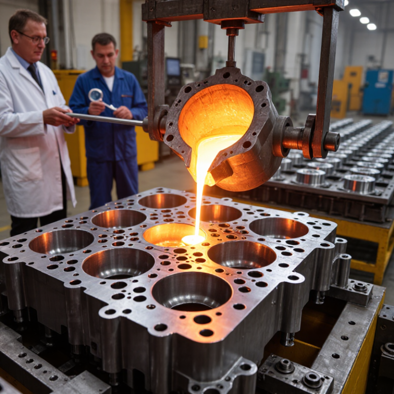
Custom Zinc Alloy Die Casting is a precise manufacturing method for producing strong, detailed metal components at scale. It uses molten zinc alloy, a reusable steel die, and controlled pressure. The process begins with melting zinc pellets in a heated furnace. A shot sleeve then pushes the liquid metal into narrow die cavities. Within seconds, the alloy fills features such as ribs, bosses, threads, and thin walls.

Dr. Steve Midson, a recognized die casting consultant and former technical director, explains, “Die casting is a manufacturing process that produces metal parts through the use of reusable molds, called dies.” His observation highlights the central advantage of Custom Zinc Alloy Die Casting: repeatable shapes with limited secondary machining. The finished part may receive trimming, drilling, plating, painting, or other surface treatment. Small details matter. A poorly placed gate can create porosity, incomplete filling, or visible flow marks.

This article examines how the process works, from alloy selection and die design to injection, cooling, ejection, and inspection. It also considers practical issues that product teams sometimes overlook, including draft angles, wall thickness, tool maintenance, and production volume. Zinc alloys can provide excellent dimensional stability and attractive surface quality, but they are not automatically suitable for every application. Engineers must assess load, temperature, corrosion exposure, tolerances, and expected service life.

The method is efficient. It is not effortless. Careful testing remains essential because real production conditions can expose weaknesses that computer models miss. With experienced design support and documented quality checks, Custom Zinc Alloy Die Casting can deliver reliable components for automotive, electronics, hardware, and industrial products.
What Is Custom Zinc Alloy Die Casting and How Does It Work?

What Custom Zinc Alloy Die Casting Is: Zamak Alloys with 3.9% Aluminum

Custom zinc alloy die casting commonly uses Zamak, a zinc-based family containing aluminum, magnesium, and sometimes copper. In Zamak 3, aluminum typically ranges from 3.5% to 4.3%; 3.9% is near the middle. This level improves fluidity, strength, and die compatibility. ASTM B86 identifies zinc-aluminum alloys for die castings and controls their chemical composition.

The process begins with melting certified ingots in a controlled furnace. A shot sleeve then pushes the liquid alloy into a hardened steel die at high speed and pressure. The metal fills thin ribs, lettering, and small mounting bosses before cooling quickly. Operators remove the runner, trim flash, and inspect dimensions. Custom tooling matters here. Poor venting can leave trapped gas, while excessive pressure may increase flash.

Industry data also gives zinc a broader context. The U.S. Geological Survey estimated global zinc mine production at approximately 12 million metric tons in 2024. That supply supports extensive use in casting, galvanizing, and manufacturing. Yet material availability alone does not guarantee a reliable part. Zamak 3.9% aluminum may offer a practical balance, but wall thickness, die temperature, and surface finish still require testing. Real production is less perfect than a specification sheet suggests.

How the Die Casting Machine Injects Molten Zinc at 10–150 MPa

Custom zinc alloy die casting begins with a steel die shaped for a specific component. The machine melts zinc alloy, commonly near 400°C, then injects it through a narrow gate. Injection pressure usually ranges from 10 to 150 MPa, depending on wall thickness, alloy flow, and surface requirements. The pressure fills tiny ribs before the metal freezes.

A hydraulic or servo-driven plunger controls this short shot. At the beginning, it moves slowly and pushes air toward designed vents. It then accelerates sharply, often within milliseconds. A final intensification stage compresses the metal and reduces shrinkage around bosses and corners. NADCA design guidance emphasizes controlled filling, proper venting, and adequate draft for stable production.

The die opens after solidification, and ejector pins release the casting. Zinc alloys can produce thin walls and detailed surfaces, supporting compact housings, handles, and mechanical fittings. Industry data from the International Zinc Association identifies die casting as a major high-volume use for zinc alloys. USGS Mineral Commodity Summaries 2025 reported global refined zinc production at roughly 14 million metric tons in 2024, showing the material’s broad industrial supply.

The process is not perfectly predictable. A slight temperature drop may create a cold shut. Excessive pressure can increase flash along the parting line. Operators must inspect shot curves, die temperature, vents, and sample dimensions together. A polished surface can still hide internal porosity. That part requires reflection.

Step 1: Designing Dies for 0.1 mm Tolerances and Complex Geometries

In custom zinc alloy die casting, die design controls accuracy, surface quality, and production stability. A 0.1 mm tolerance begins with clear engineering data, not only a detailed drawing. Designers study wall thickness, draft angles, parting lines, and expected shrinkage before cutting steel. Small errors can appear as flash, distortion, or difficult ejection.

Complex geometries need careful planning. Thin ribs, deep pockets, and sharp transitions can restrict metal flow. I have seen a beautiful computer model fail because one narrow passage cooled too quickly. Simulation can reveal air traps, cold shuts, and uneven filling. Still, simulation is not perfect. Toolmakers should compare it with prior casting results and practical shop experience.

The die may require slides, lifters, replaceable inserts, or controlled cooling channels. Each feature adds cost and another possible failure point. Measuring critical surfaces with coordinate equipment helps verify the 0.1 mm requirement. Temperature also matters. A die that is slightly too cold may produce incomplete details, while excessive heat can accelerate wear. We sometimes overtrust nominal dimensions. Real production includes tool wear, machine variation, and operator adjustments. Designing inspection points into the die plan makes these changes visible before they become repeated defects.

Step 2: Melting Zinc Alloys at Approximately 385–430°C

In custom zinc alloy die casting, Step 2 turns prepared alloy into a controlled liquid. The furnace commonly reaches approximately 385–430°C, depending on alloy chemistry and machine setup. This range supports smooth filling without excessive thermal stress on the die. The exact target matters. A few degrees can affect flow, surface finish, and tool life. Temperature alone is not enough.

Operators monitor the bath with calibrated thermocouples instead of trusting the furnace display. They check stable readings, clean metal, and suitable holding conditions before injection. Oxides and dross may float on the surface, so careful skimming helps reduce inclusions. Moisture must stay away from molten zinc. Even a damp tool can cause violent splashing. The process is less tidy than diagrams suggest. Temperature can drift when cold ingots enter the furnace or when production pauses.

A skilled team adjusts gradually rather than chasing every reading. Excessive heat may increase oxidation, energy use, and die soldering. Insufficient heat can cause misruns, cold shuts, and incomplete details. Alloy composition, die temperature, and injection speed also influence the final result. A perfect number on paper can still produce a poor casting. Recording melt temperature, holding time, and adjustments helps engineers trace defects and improve the next production cycle.

What Is Custom Zinc Alloy Die Casting and How Does It Work? — Step 2: Melting Zinc Alloys at Approximately 385–430°C
Process Dimension Typical Data or Range What Happens During Melting Process Importance
Common Zinc Alloy Families Zamak 3, Zamak 5, and ZA-8 are widely used zinc die-casting alloy families. Each alloy is charged into a melting pot or furnace according to its specified composition. Alloy chemistry affects fluidity, strength, dimensional stability, corrosion behavior, and casting temperature.
Approximate Melting Range 385–430°C Zinc alloys soften and transition from solid metal to a fully liquid state within an alloy-dependent temperature range. Heating must be high enough to create a consistent liquid melt without unnecessarily increasing oxidation or energy consumption.
Example: Zamak 3 Solidus approximately 380°C; liquidus approximately 387°C. The alloy becomes fully liquid shortly above its liquidus temperature. Its relatively narrow melting interval supports controlled melting and stable die-casting operation.
Example: Zamak 5 Solidus approximately 380°C; liquidus approximately 387°C. The alloy is heated until all charge material is fully molten and the composition is uniform. Compared with lower-strength zinc grades, its alloying additions can provide increased strength and hardness after casting.
Example: ZA-8 Melting range is typically around 375–405°C, depending on the exact specification. The alloy requires temperature control appropriate to its higher aluminum content. ZA-8 can provide higher strength than many conventional zinc die-casting alloys but may require different process settings.
Typical Holding Temperature Approximately 410–430°C After melting, the liquid metal is commonly held within a controlled temperature window before injection. This range helps maintain fluidity while limiting excessive overheating, dross formation, and thermal degradation.
Heating Method Electric resistance, induction, or gas-fired melting equipment. Heat is transferred to the metal charge until the alloy reaches a homogeneous liquid condition. Stable and evenly distributed heating reduces local overheating and improves melt consistency.
Temperature Monitoring Immersion thermocouple, infrared measurement, or furnace-integrated temperature control. Operators verify the actual metal temperature rather than relying only on furnace settings. Accurate measurement helps prevent cold metal, incomplete filling, excessive flash, and unnecessary oxidation.
Melt Homogenization Complete liquefaction followed by controlled circulation or gentle mixing, where permitted. Undissolved pieces and temperature gradients are eliminated before the melt is transferred or injected. A uniform melt supports consistent mechanical properties and repeatable part dimensions.
Oxidation and Dross Control Keep the melt covered when possible and remove surface dross at controlled intervals. Air exposure can produce zinc oxide and other oxide-rich material on the melt surface. Removing dross helps reduce inclusions, surface defects, and loss of usable metal.
Charge Material Clean certified ingot, controlled internal return material, or an approved combination. The charge is inspected for contamination, excessive moisture, and unapproved alloy mixing before heating. Clean, traceable charge material helps maintain the intended alloy composition and casting quality.
Moisture and Safety Control All tools, ladles, molds, and charge materials must be dry and preheated as required. Any trapped moisture can rapidly vaporize when it contacts molten zinc alloy. Dry equipment reduces the risk of splashing, steam-related hazards, and casting defects.
Transfer to the Die-Casting Machine Transfer temperature is generally maintained within the approved alloy and machine process window, often near 410–430°C. Molten zinc is delivered to the shot sleeve or injection system with minimal temperature loss and contamination. Consistent transfer conditions help the metal fill thin sections and reproduce detailed die features.
Main Quality Check Verify temperature, alloy identity, melt cleanliness, and absence of visible unmelted charge. The melt is released for injection only after process checks meet the defined control limits. Pre-injection verification reduces porosity, cold shuts, inclusions, dimensional variation, and rejected castings.

Step 3: Ejecting, Trimming, Finishing, and Inspecting Cast Parts

After zinc alloy solidifies inside the die, ejector pins push the casting from the cavity. The operator checks whether it releases cleanly. Sticking may indicate uneven cooling, excessive draft, or damaged tooling. Small changes can matter.

Trimming removes runners, gates, and visible flash. A controlled saw, press, or rotary tool prevents damage near thin walls. Operators then deburr sharp edges and clean residue from recessed areas. Finishing may include polishing, tumbling, coating, or light machining, depending on the part’s function. Not every surface should look mirror smooth. A functional contact area may need controlled roughness. I have found that rushing this stage often creates scratches that inspection catches later.

Tips: Use dedicated gauges for critical dimensions. Inspect the first pieces closely, not only the final batch. Check holes, threads, edges, and mating faces under consistent lighting. Measure part weight when porosity is suspected. Keep inspection records with tool settings and material details. This makes problems easier to trace, although records are sometimes incomplete in busy production periods. A second review can expose missed flash or slight warping. Good inspection combines measurements, visual checks, and practical fit testing.

Custom Zinc Alloy Die Casting: Post-Casting Process Time

A representative cycle-time profile for ejecting, trimming, finishing, and inspecting zinc alloy die-cast parts. Actual times vary with part size, geometry, automation, and surface requirements.

Ejection is typically brief, while trimming and finishing remove gates, flash, and visible surface imperfections. Inspection verifies dimensions, appearance, and casting integrity before shipment.

Get a quote
Open chat
1
Hi! How can we help you?
Chat with Pelican Containers